Re-wiring
This guide was originally
created to show users how to replace and re-wire the user side internal
telephone cabling with Category5e/6 cable in an attempt to reduce interference
that could hinder broadband services like xDSL.
However is now updated with
other tips and tricks to improve line stats further.
Contents
Front Cover.................................................................................. 1
Contents Page.............................................................................. 2
Introduction................................................................................. 3
The Rules..................................................................................... 4
Cable Education.......................................................................... 5
Tools and Items Needed.............................................................. 6
Getting Started............................................................................. 7
Extension Wiring...................................................................... 22
Ring what?................................................................................. 30
Help with Extension Wiring.................................................... 39
Other interesting stuff/notes..................................................... 41
Bibliography.............................................................................. 42
Introduction
Hi, the first thing a lot of people will
be wondering is why!?! The answer is simple. With rate adaptive services
becoming common in the
So… having more speed for your money is a
good incentive! But there are other factors that can play into it. RF
Interference - Electro Magnetic Interference (EMI) from devices as simple as an
AM radio can interfere with xDSL signals and this can be very annoying, and can
result in slower connection speeds, and even connection drops. Some other
examples of devices can be an old TV (or even a neighbours’ TV next door), a
radio, lighting (some Christmas lights can be especially bad). Here is a memo
that BT passed to ISP’s;
“It has come to BT's attention that an
extremely small percentage of seasonal lighting, which can be used both
internally and externally, may cause interference with the broadband service.
When the lighting control unit is set to any mode other than a steady state it
may generate high levels of radio frequency noise and may cause the broadband
service to lose synchronization.”
Other reasons could be that the carpet installers
nailed and stabled though your phone line, which can not only slows your rate
adaptive xDSL service down or make’s it inoperable
but it can also interfere with your POTS (Plain old telephone service).
Another reason for rewiring with cat5e/6
is that a lot of users will have poor quality telephone cable such as none
twisted pair ALARM cable, this cable just wasn’t designed to carry xDSL signals and should be replaced if it’s causing a fault
or hindering performance.
So you now want to learn how? Well first
there are some rules. But before the rules I must just point out that I am
going to add material from other sources (all listed throughout and at the end
of this document), along with notes, comment’s and pictures from myself. If
things seem repetitive, don’t worry it’s simply because I want you to
understand it fully and not make a total cock-up of it all.
The task is very simple, just read the
WHOLE guide before starting with anything, and make sure you understand it all,
especially the rules…
The Rules
and Main points
Just before the rules there is one main
point, if it’s not broke, then don’t fix it! As it is probably not worthwhile
replacing good quality twisted pair telephone cable, that is in a good
condition and well terminated, replacing cable in that state with cat5e/6 can
show very little or no improvement.
If you know how to get your line-stats
from your modem/router then do so, then if an NTE5 Master Socket (covered later
in this guide) is fitted, take the line-stats from test socket and compare. If
a big improvement is seen, due to the poor extension cabling etc, then rewiring
could be a good decision to make.
1) If you do not know what you’re doing;
pay a professional to do it.
2) You must NOT replace or move any of BT’s property; this
includes but is not limited to the following;
- The Drop cable – The cable that come’s from outside to the
inside.
- A junction box – If it is before the BT master socket.
- Cable before the BT master socket.
- Cable after the BT master socket (if BT holds ownership).
The Master line box is the "demarcation" point between your telephone equipment, wiring and BT's Exchange Line.
The reason this is so, is that everything on your side of the master, is your problem. Everything on BT's side, including the Master line box itself, is BT's problem. It needs to stay this way!
Now if you want to something along the lines of; move the Master socket (to get rid of the crap wire between that junction box and master socket) or to relocate the Master socket to where the drop cable enters your premises, then to do this is YOUR choice, if you mess it up, then you will need BT to sort it out, IF they sort it out for you that is (keep reading).
If you successfully move your Master socket to have more “high quality user-side wiring” then good for you, but it is ILLEGAL to do this, if it is clear and obvious that you moved it yourself and BT issue’s a fine and/or terminate your line. Don’t say you weren't warned.
That was the warning… just in case you didn’t understand the ILLEGAL part.
3) When inserting wires into IDC terminals, use the correct tool! DO NOT use a flat blade headed screw driver, as this pushes the blades apart and doesn’t make a good connection in the wire (if it makes a connection at all!).
The whole point of this exercise is to upgrade your normal or damaged cable to high quality cable, but badly terminated connections (by not using the correct tools!) can make it worse that just using rubbish cable.
So when wiring to IDC terminal’s please use the correct tool, as IDC tools can be found as cheap as 49p!
4) Your new Category 5e/6 cable must be SOLID core cable. Most cable you buy over 10meters is usually solid core, but check! This is very important because the IDC connectors are not designed to terminate STRANDED core cable.
5) Rule 5 – this rule is an easy one, and it’s to ensure you read every word in this guide.
You must understand it all, before doing ANYTHING!
If you find yourself breaking this rule in anyway, then you MUST follow rule 1. J
Cable
Education
The list below shows the current versions of category cable
Cat 1: Currently unrecognized by TIA/EIA. Previously used for POTS telephone communications, ISDN and doorbell wiring.
Cat 2: Currently unrecognized by TIA/EIA. Previously was frequently used on 4Mbit/s token ring networks.
Cat 3: Current cable standard, used for data networks utilizing frequencies up to 16MHz. Popular for 10 Mbit/s Ethernet networks.
Cat 4: Currently unrecognized by TIA/EIA. Provided performance of up to 20MHz, and was frequently used on 16Mbit/s token ring networks.
Cat 5: Currently unrecognized by TIA/EIA. Provided performance of up to 100MHz, and was frequently used on 100Mbit/s Ethernet networks. Suitable for 1000BASE-T gigabit Ethernet.
Cat 5e: Provides performance of up to 125MHz, and is frequently used for 1000BASE-T gigabit Ethernet.
Cat 6: Defined by the ANSI TIA/EIA 568B-2.1. It provides performance of up to 250MHz, more than double category 5 and 5e.
As you can see CAT5e cable supports frequencies up to 125MHz and with ADSL running at up to 1.1MHz, ADSL2+ at up to 2.2MHz and VDSL2 into double figures.
So using CAT5e/6 for your extensions
defiantly means it will be stable, and due to the high quality of the cable, interference
at the lower frequencies will be reduced, as all category cable is backward
compatible.
|
Pair |
Colour |
Pair |
|
1 |
BLUE |
1 |
|
2 |
|
2 |
|
3 |
GREEN |
3 |
|
4 |
BROWN |
4 |
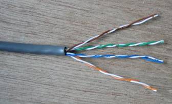
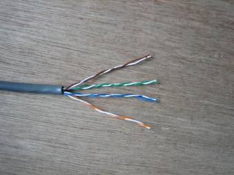
Above shows the colour of the pairs found
in CAT5e/6 cable, and lists the number of the pair.
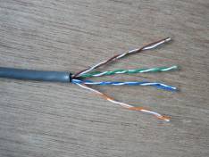
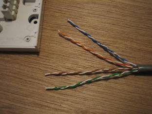
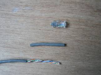
Below shows a picture of some gray solid
core CAT5e cable with the outer sheath removed to show the twisted pairs.
Tools
and items needed
Items needed are going to be tools/equipment, time, and of course… cable.
- A flat headed electricians’ screw driver.
- A small cross headed Phillips screw driver.
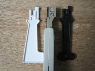
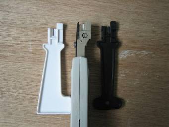
- A “Krone-type" IDC (Insulation displacement
connector) Punch-Down insertion tool. This can be a cheap plastic one (the
blade wears out after about 6 insertions so try get one for every socket)
or the better metal one (it lasts!) The correct tool can also come with a
hook for removing wires from existing IDC terminals, and a flat headed
screw driver for unscrewing the socket plates.
It can be purchased at http://www.clarity.it/acatalog/punchdown_tools.html or in B&Q. - Catagory5e/6
network cable, this must be solid-core cable, not stranded or it will not
connect/terminate correctly to the IDC terminals. Up to 30metres of PLAIN
WHITE! can be purchased from
http://www.clarity.it/acatalog/custom_cat5_network_cable.html
however Belkin also sell up to 30metres of white Cat5e cable (but has writing down one side) this is slightly cheaper, you just cut the plugs off, and make sure the writing is facing the wall/or cable under the carpet. It can be purchased from places like
http://www.ebuyer.co.uk/ and many more places, the cable colour can be whatever you like, but it must be solid core cable not stranded. - Found a place to get a huge amount of Cat5e cheap, 305meters of it, in white,
- A hammer – to secure your cable with cable clips.
- Cable cleats/clips – these should be 5mm for Cat5e and I think 6mm for cat6 and can be purchased from many places, B&Q, even at http://www.clarity.it/acatalog/adsl_extensions.html
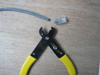
- Wire cutters – to cut the cable at desired lengths, to remove the outer sheath of the cable, and to trim the end of the cable once inserted into the IDC terminals if disposable IDC tools are used.
- Wire stripers – to strip some sheath from wire when wiring a custom NTE5 line-box.
- Pen/Paper - to make notes and stuff, if you need too.
Of course you can purchase any of your items from the place of your choice.
Getting Started
When in possession of all your tools and have the amount cable needed, your first thing is to make a map of your current wiring setup; this is done to just help you know what you’re replacing. Doing this can also help you understand rule2 (see above) make sure you know what is yours to replace, and what is BT’s. Please make sure you read this entire guide before starting, as you do not want to get halfway thru and then end up getting stuck.
Next I am just going to go through some basic socket education.
No matter what type of socket you have, they are very simple to understand.
This table shows the main types of sockets you should find in your premises.
If it is different, try do a little bit of research before starting.
“LJU = Line Jack Unit”
|
LJU1 |
Dimensions: 55 mm x 55 mm x 25 mm |
|
LJU1/1A |
Master IDC Socket, with a capacitor, resistor and surge
arrestor. |
|
LJU1/3A |
Secondary (extension) IDC socket without any components fitted. |
|
LJU1/4A |
Master screw terminal version of LJU1/1A. |
|
LJU1/6A |
Secondary screw terminal version of LJU1/3A |
|
LJU2 |
Dimensions: 68 mm x 68 mm x 25 mm |
|
LJU2/1A |
Master IDC Socket, with a capacitor, resistor and surge
arrestor. |
|
LJU2/2A |
PABX Master IDC Socket, with a capacitor, but no resistor or
surge arrestor. |
|
LJU2/3A |
Secondary (extension) IDC socket without any components fitted. |
|
LJU2/3C |
Secondary (extension) IDC Socket is as a 3A but with reverse
configuration (left latching), designed to accept 430/630 plugs rather than
the normal 431/631 plugs. |
|
LJU2/4A |
Master screw terminal version of LJU2/1A. |
|
LJU2/5A |
PABX Master screw terminal version of LJU2/2A. |
|
LJU2/6A |
Secondary screw terminal version of LJU2/3A |
|
LJU2/7A |
Master for a table top payphone (contains an earth connection
for lightning protector) |
|
LJU3 |
Dimensions: 85 mm x 85 mm |
|
LJU3/1A |
Master IDC Socket, with a capacitor, resistor and surge
arrestor. |
|
LJU3/2A |
PABX Master IDC Socket, with a capacitor, but no resistor or
surge arrestor. |
|
LJU3/3A |
Secondary (extension) IDC socket without any components fitted. |
|
LJU3/3C |
Secondary (extension) IDC Socket is as a 3A but with reverse
configuration (left latching), designed to accept 430/630 plugs rather than
the normal 431/631 plugs. |
|
LJU3/4A |
Master screw terminal version of LJU3/1A. |
|
LJU3/5A |
PABX Master screw terminal version of LJU3/2A. |
|
LJU3/6A |
Secondary screw terminal version of LJU3/3A |
The main difference upon looking at an LJU style line-box is the size of the unit; all can be different in terms of how they are mounted to the wall. Most users will have an LJU style master / or an NTE5 master and an LJU slave (secondary extension), that is, if any extensions are installed.
Of course if you do not have any extensions then you have no user-side wiring to replace, as the only wire you as the end-user are allowed to replace is the cabling after the Master socket, have a look up at Rule-2. As you may have guessed you can learn a lot from this guide, but you have already been warned if you are attempting to do something along the lines of; Relocate the Master nearer to the drop-cable (where BT’s cable enters the premise), and then using cable such as Cat5e/Cat6 to a new extension (where your Master Socket was originally situated)
Again I will point out you are NOT allowed to do this; as it would breach your contract with BT, just contact BT and get them do it, simply ask for a Master Socket relocate.
If you’re looking to install your own extensions, then this guide does cover how to do this (but not the DIY side of it), if you are looking to use Category5e/6 cable then you’re a wise person. J
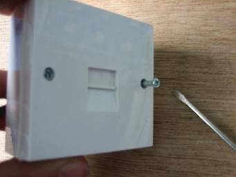
Take a look at all the pictures of the front and back of the sockets, familiarise yourself with them and your own equipment.
This guide will show you how to wire your extensions from an NTE5 type master socket using Cat5e/6 cable. If you have LJU type master socket and wish to use an NTE5 ADSL face plate, you are not out of luck! The NTE5 can be installed legally by the user.
(Or contact BT and they will fit one for around £30)
This guide shows how
to wire the extensions in IDC terminals not the Screw types.
Extra Note: If you
have an LJU style Master line-box, they are exactly the same as the LJU
extension sockets apart from the extension sockets do not have components inside,
So wiring to them is
practically the same as wiring to NTE faceplate or extensions.
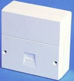 Now
nearly every BT Master line-box installed since around the 1980's has been this
kind.
Now
nearly every BT Master line-box installed since around the 1980's has been this
kind.
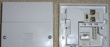
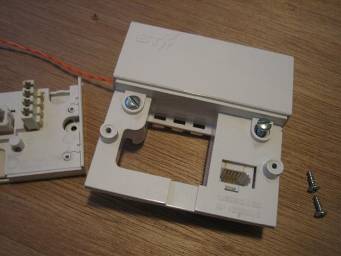
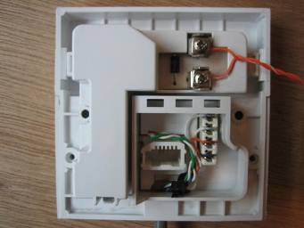
As you can see, the lower half is separate in three sections. The rear section
on this picture is the surface mount "back-plate" however this could
be embedded in the wall as a flush mount. The top front section is the front,
this holds the master components.
The separate lower front panel is the "face-plate” / “front-plate".
So if your BT master socket isn't this type, then devices
like ADSL-Nation’s superb XTE faceplate adaptor and BT’s NTE5 ADSL adaptor faceplate
are of NO USE to you, as they replace the lower front half of the NTE5
unit, with a face-plate that contains the filter components.
If you wish to use an ADSL-faceplate then you just wire one up as normal, depending on what kind of extension setup you want, (this is explained in the included instructions)
If you would like to acquire and fit your own NTE5 line box, you can still
legally do so.
As long as your not breaking Rule-2 by replacing the current BT Master Socket with your own
custom NTE5.
Many places sell NTE5 units.
Austin Taylor sells NTE5’s.
Get to http://www.austin-taylor.co.uk/pages/nte5.htm
Clarity.it sells NTE5's.
Get to http://www.clarity.it/acatalog/lineboxes.html
Solwise.co.uk sells NTE5’s, other items and tools.
Get to http://www.solwise.co.uk/telesun.htm
Many more places will sell or resell the NTE5 Master Line Box, but again these are not BT Master Sockets, and as said, should not be used to completely replace the BT Line box.
I will cover this fact in more detail below; this is a side note about the rear of the NTE5 and its faceplate.
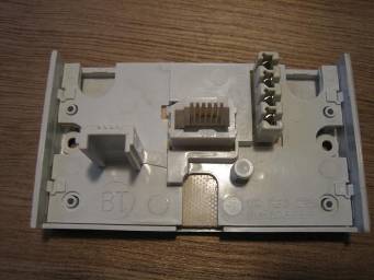
Below shows a picture of the same NTE5 shown above found on Google Image search, this time it shows the rear of the NTE5 Socket.

For more pictures, read my section on wiring the NTE5, but take notice that on the NTE5 above, you can see six terminals on the face plate.
Some may have 1-6, some have 2-5 (as 1 and 6 do not do anything anyway, and ADSL faceplates usually come with 2-5 and AB (not the BT AB connectors) the AB connectors on the ADSL faceplates are used for extensions as terminals 2 and 5 are, they are for if you choose to have ADSL and VOICE or just VOICE services on your extensions or not.
When using an ADSL faceplate, I will point out that when using the AB connectors for extensions instead of 2 and 5 connectors, the wire you would place in 2 connects to B, and the wire you connect to 5, connects to A.
You must not completely replace the BT master socket with a
custom NTE5 unit, as rule-2 says.
Replacing your BT Master Socket with a custom NTE5 is a breach of BT
regulations and is illegal, and you could face consequences as described in rule-2.
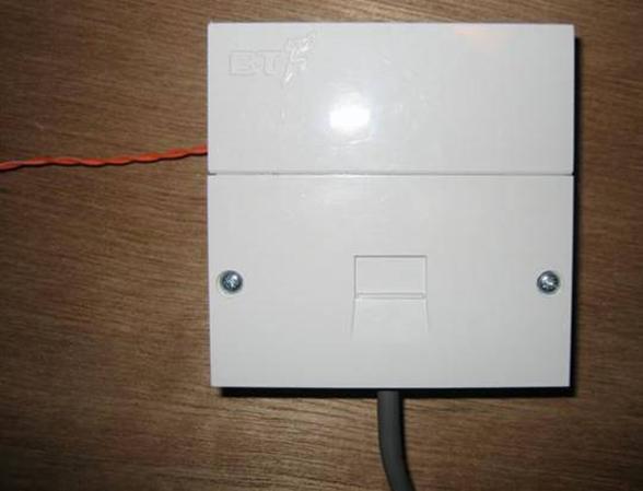
How will BT tell? Well for starters only the BT installed NTE5's have the little BT logo in the top left of the unit, the logo can be a T in a circle with two dots at the right section of the T the T logo can appear in the top right of the unit, or more recently the BT Piper logo (as shown on the NTE5 I use in the wiring section).
Note: the built in BT logo in the top left corner. (As said this can be a T in a circle also)
If you are
without a BT NTE5 style Master Line Box, and unable to use the BT ADSL
faceplate, or ADSL-Nations XTE2005 ADSL face-plate instead of micro-filters,
then here is how to add your own custom NTE5 as purchased from any the places
listed above.
Again; RULE-2!
All you have to do is install your custom NTE5 master socket as the very first
extension off the BT Master socket, and then install your extension sockets
from your custom NTE5.
Basically, you have your BT Master
socket, going to your custom NTE5, going to your extensions. Simple!
Below is a simple drawing I made
in MS-Paint of what I just said above;
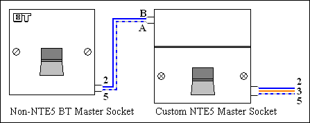
The diagram should be self-explanatory as it shows what colours go where. If
you do not understand that diagram then you are breaking Rule-5 and should follow Rule-1,
then you get a BT NTE5 anyway which replaces the LJU style, and then there is
no fuss at all.
I do actually recommend spending
the small amount to get BT to replace your old style master socket with an NTE5
master socket, as it just makes things a lot simpler.
However…
The exchange line connection
points on the rear of the NTE5 unit, are two screw plate terminals marked A and
B (as shown how to wire later on). Connect extension wires 2 & 5 (Blue and
White/Blue) from the BT Master to these terminals, and you now have a working
NTE5 Master Socket. Now you can fit an ADSL face plate and/or wire your
extensions.
All you are doing is pretending
the custom NTE5 is really your real master socket.
As said in Rule-2 an existing
extension cable running from a non-NTE5 master socket to an extension socket,
might also be BT property and technically
you should not move or replace it.
If a BT engineer ever comes round,
and you've replaced your BT master socket illegally with a non-BT master socket
then he/she is likely to issue one of the two consequences I mentioned in Rule-2, but they probably would not be
bothered about the extension cabling. So
if you're not sure about the ownership of an existing extension and the cable
after the master socket, then you should come get BT to remove it, like before
if BT come round they will probably install an NTE5 anyway, so then no need for
the custom NTE5. The choice, as always, is yours.
Now if you do not have any extensions
and you are installing extensions from the LJU style master box you will need
to know how the cabling works on the back of it.
|
Pin |
Use |
Drop Cable. |
Master Socket |
1st Secondary Socket |
2nd Secondary Socket |
Pin |
|
1 |
Not used |
None |
Green/White |
Green/White |
Green/White |
1 |
|
2 |
'B' wire (-50V to earth) |
|
Blue/White |
Blue/White |
Blue/White |
2 |
|
3 |
|
None |
Orange/White |
Orange/White |
Orange/White |
3 |
|
4 |
Earth (PABX use only) |
None |
White/Orange |
White/Orange |
White/Orange |
4 |
|
5 |
'A' wire (0V to earth) |
White |
White/Blue |
White/Blue |
White/Blue |
5 |
|
6 |
Not used |
None |
White/Green |
White/Green |
White/Green |
6 |
The above shows how the drop cable wires go to pins 2 and 5, (these you should not touch)
Note: The incoming cable wires before the master socket could be any colour, not just Orange or White, if it's a second line then they might be a Green or Black pair, or even Red/Slate, or Blue/Brown, maybe the incomer is not drop wire at all, so might be Blue –White/Blue or Red - Blue on even older cables, but you shouldn’t be touching them anyway!
If wiring from an LJU style master, you can wire up to the LJU extensions using those colour codes as shown in the table above.
(When using Cat5e/6) you have 4 twisted pairs (8wires)
|
Pair |
Colour |
Pair |
|
1 |
BLUE |
1 |
|
2 |
|
2 |
|
3 |
GREEN |
3 |
|
4 |
BROWN |
4 |
Four pairs, 8 wires, 4 coloured, 4 white with colours mixed on.
On your phone cable you usually will have BLUE/WHITE and WHITE/BLUE, this means when BLUE comes first, it is mainly BLUE with WHITE splodges, and visa-versa.
On Cat5e/Cat6 the First colour is usually solid with no white splodges.
1=GREEN
2=BLUE
3=
4=WHITE/ORANGE
5=WHITE/BLUE
6=WHITE/GREEN
(and you have BROWN and WHITE/BROWN) as a spare pair if
needed at a future date.
That’s it for me explaining on LJU style
masters, if going from an LJU master to a custom NTE5,
The Blue wire on pin2 goes to the B connector on the back of the NTE5
And the White/Blue wire on pin5 goes to the A connector on the back of the NTE5.
Now if you have a BTNTE5 or a custom installed NTE5 (see above) then you are all sorted and ready to start the rewiring of your user wiring. If no NTE5 is installed, the next section explains all about installing an NTE5, and the user-wiring. If wiring from an LJU type Master Socket, then that is covered later on.
The face-plate on the NTE5 connects user side wiring to the Master socket by the dummy plug, this goes into the test socket (this is the socket used to test if your user-side wiring is at fault). Before you begin you may want to get the “line stats” from your modem/router, so you can do a before and after. The choice is yours.
However if your line-stats taken from your extensions/face
plate, are the same as in the test socket, then no improvement will be found
when rewiring to cat5e/6.
The following assumes your master socket is an NTE5 type if it’s the LJU style
and you do not wish to install a custom NTE5 then just follow what is said, and
mainly look the how to wire extensions (below) because the LJU style extensions
are the same as the LJU style master, apart from the extensions do not have the
master components fitted.
The NTE5…

I am first going to show you how to wire up your custom NTE5,
Note: I must point out again, read this entire guide before doing anything!
If you have a BTNTE5, then all you will be doing is inserting user-side wiring to the front plate so browse down (or just read on if you are interested).
The information shown here must not be used in violation of RULE-2!
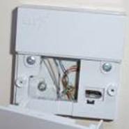
Below shows a picture of the rear of the whole NTE5 unit.
First loosen the A/B screw in plates by unscrewing them slightly.
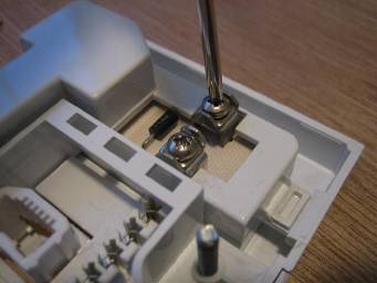
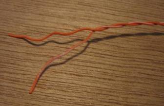
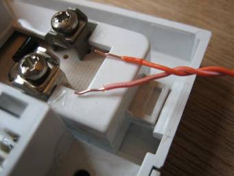
Below shows my simulated A/B wires, Orange being the B wire and the White being the A wire (its Orange/White because I am using an orange pair from some Cat6 cable)
However your simulated A/B wires should be the Blue/White blue pair coming from your BT LJU style master socket.
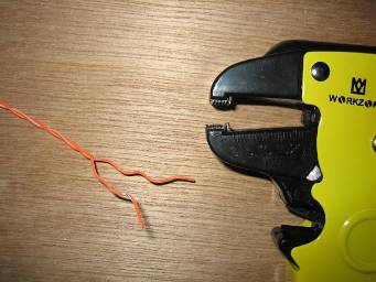
Strip around 10mm of sheath from the wire to show the core, (this is the only time you will need to strip any sheath from the main core wire.)
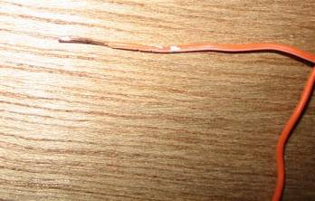
Here shows the wires solid core with some sheath removed.
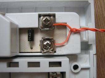
Next thread your cable under the screw in plates, like below.
Now I do this section so that more cable is making a contact, and a BT engineer has corrected me (see how to do it the BT way in the next few steps). But bend the core of the cable around something small, (like the higher metal part of your screw driver.) see below for the results.
Next gently pull the wires back so the two “hooks” you just made are around the screws,
Once ensuring that no wire with sheath is under the plate, and ensuring that as little cable is untwisted as possible. Screw the plates down tight.

(A small wire-tie can be placed around here. Securing the wires)
A “BT bod” is trained to strip back and then 'fold' back the exposed wire this then just goes under and through one side of the NTE screw in plate, not 'hooked' round as I showed.
The picture below shows the exposed core of the wire more clearly.
If doing it the BT way, follow as said above, or just do the “hooked” method as above, or place the core of the wire under the plate of the NTE screw.
And your done, the A/B cable will go away outside/or to your BT master socket, and yes! As you can see, this is a BT NTE5 I am working on, so thanks to the BT engineer again for supplying me with that for the purpose of helping you all with xDSL J

Now onto the main part, wiring the NTE5 face plate with Category5e/6 twisted pair solid core cable, an how many pages in are we before I got here!?!
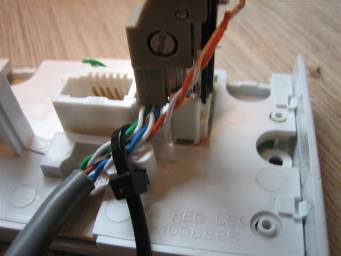
Below shows a standard face-plate, yours could be different as it could have six terminals or it could be an ADSL-filter plate.
Remove some outer sheath from your cable (see extension section as I show how in more detail) (so yes READ all of these sections). Around two inch’s should be enough.
Now place the pairs along side of the little holder if there is one and secure
them with a wire tie, but take note, not to pull it really tight just yet, and
it will need rotating or the faceplate will not fit into the socket. Lay the
green and brown pair, around the top of socket out of the way like shown. (If
your face-plate is different it is up to you what you do with them), I am
keeping them there so you have a spare pair at least, if something goes wrong
in the future.
Trim the Green and Brown pair down, but not too short as that they can never be used.
Choose your cutter, you can be using disposable cheap IDC terminators or the actual tool, the choice is yours. I will be using the correct tool as it has little cutters, (see extension section as I demonstrate its use in more detail) (so yes READ all of these sections)
Undo the twists in the pairs as much as is necessary, and lay the wires flat across the correct IDC number, Blue over terminal 2, White/Blue over terminal 5.
Next just simply push down with your tool - all the way down.
Continue to do the other wires, if you are not connecting the ring wire (see Phil’s section for reasons for not connecting this, near the end of the guide) then just move it aside.
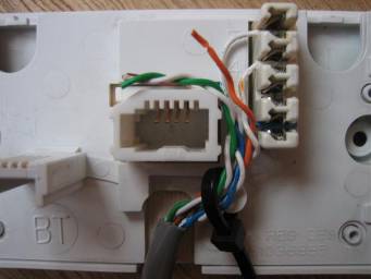
If connecting the ring wire, then do so.
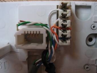
When done it should look like this…
Note at the bottom, I have pulled the cable tie further around. Look at the picture of the complete NTE5 unit to see why…
See how at the bottom there isn’t very much room…your face-plate would not have been able to plug into the socket as the cable tie end would have blocked it.
Above shows the NTE5 all done. Apart from you should be using white Cat5e/6 cable (looks nicer in the home/office, but it depends how you want it to look) and the A/B wires will be behind the wall in a flush mount or something. Or the drop cable or what ever could come though a surface mount, either way, it doesn’t matter because this guide is showing you how to wire… remember rule 2?
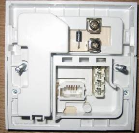
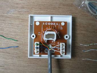
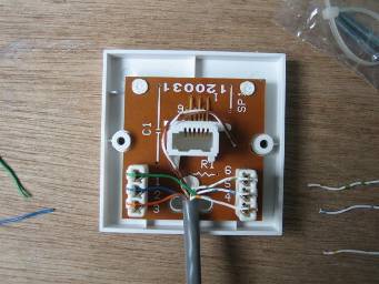
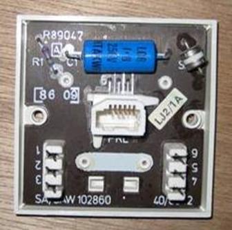
Now onto the extensions, the following socket shown in the pictures is the LJU2/3A socket.
Here is a picture of the LJU2/1A (Master IDC) and LJU2/3A (Secondary IDC)
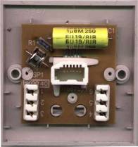
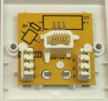
(The layout of the PCB can change, so your components can be in different places.)
Assuming you have cut your cable to the right length, and everything is good to go, let’s wire them up.
Cut the plug off the other end, (or if you have a huge amount of cable just cut it when it’s the correct length.)
Now thread the cable through the back-plate of the extension, or if it is a flush mount or surface mount… which ever.
Strip around two inch’s of outer sheath to reveal the twisted pairs.
Then untwist the pairs (as shown below)
Choose your weapon… For the extensions I am just going to use the proper tool as it has the little cutters.
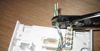
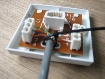
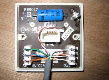
Untwist the pairs and lay the correct colour over the correct IDC number (see the list above) you could also wire-tie your cat5e at this time (go down a few pictures to see).
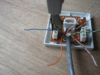
Start to push down and the cable will be terminated in the blades.
Keep pushing to close the cutters and they will snip the excess cable off.
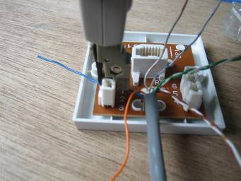
Now at this point, you can decide if you wish to leave the ringer off (as you can with the NTE5 face-plate),
I connected the green pair and pin4 for neatness. You can just choose to wire the blue pair in to terminals 2 and 5.
Just tuck it up around the socket like I have done with the brown pair, you can choose not to wire the ring wire to pin3 at the master or at all the extensions.
Personally I would wire it all at the extensions and leave it off at the master if you are one of the people who would like to disconnect the ring wire. This would make it so when you wanted to connect the ring wire, you just have to connect it at the master and then you’re done, rather than open all of the extensions to reinsert.
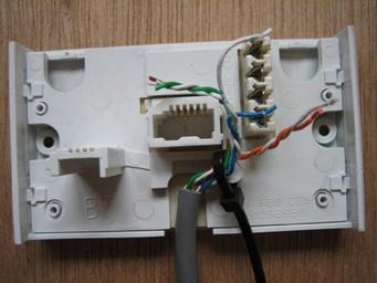
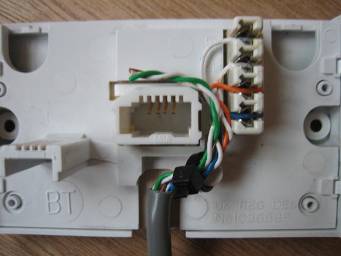
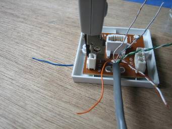
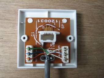
If you are just going to wire all of the contacts then it should now look like below.
Next is to secure the cable to the front of the socket, this can be done first or last or whenever… just make sure its done so yanking on the cable wont cause all of your wires to rip out of the IDC’s.
Pull it tight (but not so it crushes the Cat5e/6). Then just cut the excess tie off.
Next screw the face plate back onto the back plate/wall mount/which ever (I am showing how to rewire), so if you are installing extensions, you should have the basic DIY skills needed to screw the thing to the wall ;-)
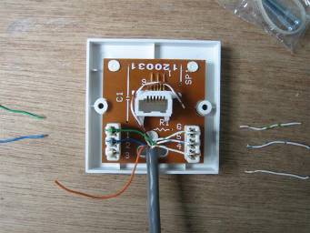
Now here is a late addition to the guide, I got hold of an old LJ2/1A (LJU
style master socket) Thanks BT!
Below shows my simulated AB wires again, Orange being the B wire and the White being the A wire (its Orange/White because I am using an orange pair from some Cat6 cable)
Here shows the master socket with no extension wiring, the AB cable should go off into the wall or off somewhere… Again the AB cable at this point COULD be blue and blue/white as sometimes BT installs the AB cable to a junction box then uses normal phone cable to the master box. (It could be any colour…!)
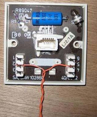
Anyway installing your cable to extensions or the custom NTE5 is easy! Just tuck the spare brown pair out of the way again. You can also leave the ring wire off terminal 3 if you wish.
After this the user wiring could go off to the custom NTE5 or to your extensions.
What’s all this about the ring wire removal then?
Many users on ADSL-Guide have found disconnecting the ring-wire from terminal 3 has improved line stats, sometimes in huge amounts. A forum member sent me this information. (I deleted your email, so email me and I will add your name to the Bibliography)
Many years ago the
The main reason for this, involved ‘pulse-dialling’, which has now been replaced by ‘tone-dialling. It was a good idea at the time because it made it possible to stop the ‘tinkling’ that occurred on other extensions when a phone was dialling.
However, there was a downside: To get the ring signal into the telephone we now have to run a third wire from the socket to the phone. Also, since we only need one ring capacitor on our line, and it is located at the 'master' socket, we have to take three wires to all our extensions, rather than the two wires which come to the house.
On most modern wiring you will find the original phone signal connected on the 'blue-white' pair of wires (Terminals 2 and 5) and the extra 'ring' signal connected on an orange wire (Terminal 3), though these colour codes are not always followed.
Now, since ADSL filters only filter the main telephone pair, they must re-generate the ring signal themselves. All of this is of only passing interest but it does mean that you only need to feed an ADSL filter with two wires. The ring signal for the third terminal on the attached phone is generated internally. Since most telephone extension wiring consists of two pairs, you may find this information particularly useful if you need to use a particular run of pre-installed cable for both a filtered and unfiltered signal (However Cat5e/Cat6 has that extra pair remember?). It is up to you if you wish to remove the ring wire, and the reasons for doing so are listed later on in a section that Phil, better known as Yarwell from ADSL-guide as written.
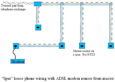
If the incoming ADSL signal is weak, or mixing with a lot of interference, it is possible that the layout of the extension wiring within your premises can degrade the signal even further.
If you suspect that this maybe a problem, then you will need to do all you can to optimise the layout of your wiring.
The basic principle is to ensure that there is only one path for the ADSL signal - from your master socket to your modem. If it is running off an extension then there should be no blind alleys caused by t-junctions or branches on the way. All of these blind alleys should be closed off with a filter so that the ADSL signal cannot pass down them.
See Yarwell’s picture he created of his star/spur wiring system.
The best solution is to put your modem next to the master socket using an ADSL face-plate. (NTE5 required). This places the filter as close as possible to the incoming ADSL signal and provides hard-wired, filtered connections at the rear for all the other telephone extension in your house.
The only place the ADSL signal is available is at the front of the faceplate. Unless you make dedicated ADSL extensions, or by using ADSL-Nations faceplate, allow for ADSL and VOICE to the extensions.
Hopefully however no matter how your wiring is laid out, the Cat5e/6 should hopefully have reduced interference with the ADSL signal.
Next we go onto the reason for removing the ring wire.
This section is all of Yarwells work, so thank him for the excellent explanations.
Most broadband in the
Nowadays ADSL is supplied "wires only" i.e. BT put the signal on the
line and the user gets to make it work. When the twisted pair phone wire
arrives in the user's house it is converted by a "master socket" to a
3-wire system where the 3rd wire provides a ring circuit, originally designed
to power clunky bells in old steam phone’s J, see the explanation
at http://www.wppltd.demon.co.uk/WPP/Wiring/UK_telephone/uk_telephone.html.
This 3rd wire is a "bit of an issue" as it makes
the nicely symmetrical balanced twisted pair into the equivalent of a 3-legged
ballerina.
In my case, the ring wire runs around my house as part of
the feed to at least 6 extension phone points, in doing so it acts as a nice
big aerial (antenna) to collect any radio transmissions and random electrical
noise that may be passing through. It then feeds this mush back into one side
of the twisted pair through the capacitor that is there to provide the ring
signal and consequently degrades the ADSL signal.
This "degradation" appears as a reduction in the signal to noise
ratio (SNR), and as CRC errors counted up by the modem and in
some cases cause disconnections, or prevents the end user getting the
speed their line should be capable of. As we move to faster speeds and to
"rate adaptive” services where the ADSL goes as fast as the line allows
it, the dear old ring wire will slow down our connections.
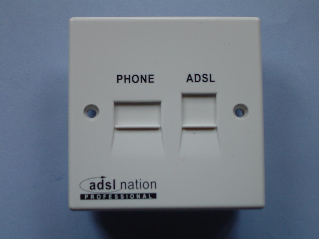
So, what to do with the 3rd wire? The Rolls Royce solution comes in the form of
an ADSL filtered faceplate (photo below)
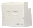
This fits onto modern BT NTE5 master line-boxes and provides
ADSL and voice on separate sockets with filtered extension wiring connectors at
the back. This keeps mush from the extension wiring, including the ring wire,
out of the ADSL signal. It also avoids the need to use micro-filters on each
telephone appliance (depending on how wired up with certain face-plates), which
is A Good Thing™. Also available from ADSLnation.com
However, many of us don't have a nice NTE5 terminating our incoming phone line.
My phone line comes into a junction box in the roof-space from which the wires
run in a "star" or spur configuration, the "master" socket
is on one leg of the spur system and is identified by having a ring capacitor
and a surge arrestor fitted.
As I have no NTE5 I can't use a filtered faceplate without a
re-wire, so a bit of innovation is called for.
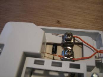
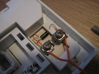
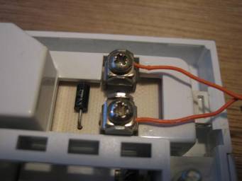
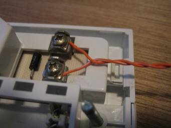
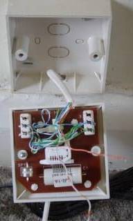
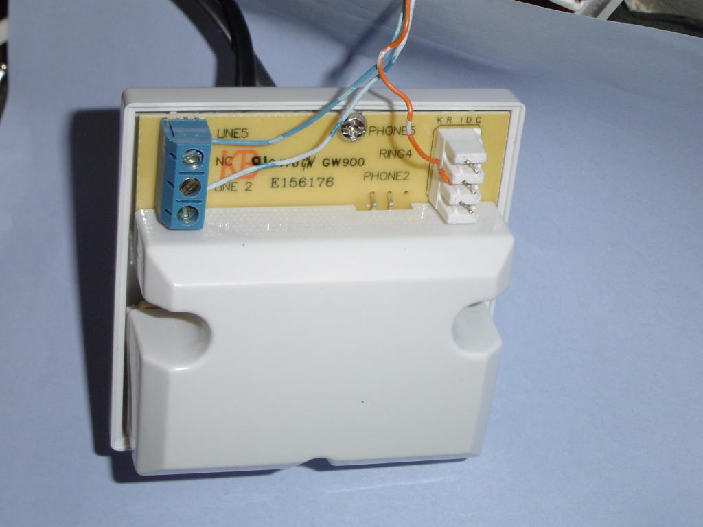
The photo on the right shows the back of my master socket with the ring wire
disconnected from terminal 3, the other half of the orange/white pair is also
disconnected from terminal 4. A higher resolution photo is at the bottom of
this article.
By disconnecting the ring wire from the master we remove the 3rd leg and
restore the balance / symmetry to the line.
Well, so much for the theory, what difference does disconnecting the ring wire
actually make? The stats from my router below show the results;
Before, with ring wire (1 hour stats)
LocalSNRMargin = 20.5 dB
LocalLineAttn = 32.5 dB
RemoteLineAttn = 23.5 dB
RemoteSNRMargin = 25 dB
LocalFastChannelCRC = 22
LocalFastChannelHEC = 6
After, ring wire disconnected (20 hours)
LocalSNRMargin = 32.0 dB
LocalLineAttn = 32.5 dB
RemoteLineAttn = 23.5 dB
RemoteSNRMargin = 29 dB
LocalFastChannelCRC = 2
LocalFastChannelHEC = 0
So we see an increase in local SNR margin of 11.5 dB, meaning the router sees
11.5 dB more of the useable signal from the exchange after subtracting the
noise. Going the other way the exchange gets to see 4 dB more of useable signal
from the router. These figures after rebooting the router so it could adapt to
the new line conditions.
20 hours after disconnecting the error counter hadn't shifted from its initial
value of 2 errors, compared to 28 CRC & HEC errors in just one hour with it
connected. Result!!!
The phones still ring because they are using micro-filters and each of these
has its own ring capacitor on the phone outlet side of the filter. If you
disconnect the ring wire it would be prudent to re-connect it if you move out
of the property, so the next occupier's phones work as expected.
Enjoy!
After the success with taking the ring wire off and improving
the SNR I was blessed with a free speed upgrade to 2M by my ISP Demon
which was facilitated by ADSL-guide getting my entry changed in BT's
line prequalification number checker.
This speed upgrade took the downstream SNR margin down to 25 dB, still healthy
but I was pleased I did the ring wire thing to improve it. Last night I hooked
the ring wire up again and the ADSL modem lost sync, it re-trained to an SNR of
12 dB and ran OK but clocked up errors. The reason I put it back on was to look
at the frequency effects of the interference, using a Sagem
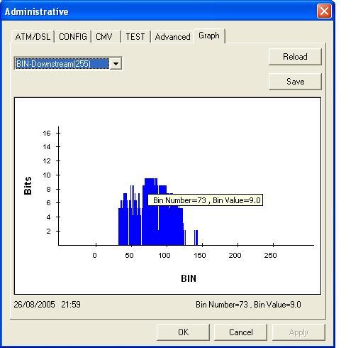
F@st 800 modem's diagnostic mode.

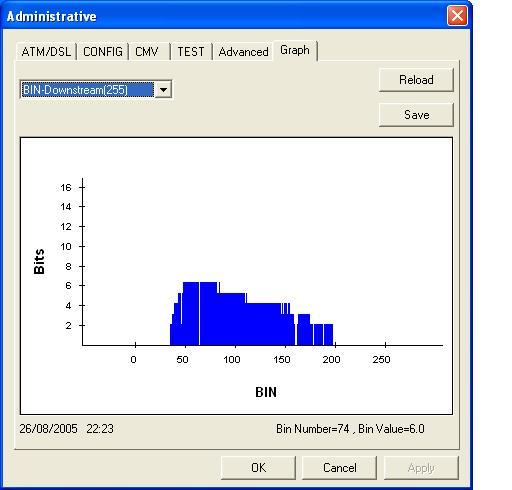
The first plot is with the ring wire disconnected, showing a
wide range of useable frequencies.
The second plot shows the effect of reconnecting the ring wire - it loses
virtually everything above frequency band 140 with a consequent loss of ADSL
data carrying capacity. The lower frequencies are a lot more ragged too. It
would still operate at 2Mbits/s but was clearly less capable than before.

With the higher frequencies rendered unusable by the ring wire interference,
the modem is forced to cram more data into the lower frequency bands. This in
turn makes it more sensitive to interference as a higher SNR is required in
order to use more bits per channel.
So at least we can see why the ring wire impacts the SNR, it is adding
interference in the 600 kHz - 1 MHz range. This is AM and short wave radio
territory, so perhaps this should not be a surprise - for all I know the ring
wire may be a nice wideband AM radio antenna, built into my house :-)
For my final experiment I hooked up a filtered socket from ADSL
Nation in place of the master. This provides a filtered and unfiltered
socket on the front, and an IDC terminal block for filtered extensions on the
back. So I used it to provide me with a filtered ring wire that could supply
ringing voltage to all the extensions without compromising the ADSL. This works
well and maintained the 25 dB SNR and over 10 hours my router only clocked 3
CRC errors.
LocalSNRMargin = 25.0 dB
LocalLineAttn = 32.5 dB
LocalTxPower = 10.5 dB
LocalFastChannelRxRate = 2272000
LocalFastChannelTxRate = 288000
LocalFastChannelFEC = 0
LocalFastChannelCRC = 3
LocalFastChannelHEC = 0
RemoteLineAttn = 22.0 dB
RemoteSNRMargin = 29 dB
The only point in doing the filtered ring wire bit, as opposed to simply
disconnecting the ring wire, is to leave the extension wiring fully functional,
such that if you aren't using ADSL any more or leave the property the phone
sockets will behave as expected. One wonders if at some point BT will abandon
the ring (3rd) wire, it may have made sense 20 years ago for electromechanical
bells but it’s a real nuisance with ADSL broadband.
The images below show the "before" bin plot with the original ringwire connected, the filtered ringwire
connection and the "after" bin plot using the filtered ringwire.
Finally, just a reminder that the above refers to star or spur wired systems where an NTE5 master socket can't
be fitted. The NTE5 filtered faceplate is the preferred solution where
it can be used, it incorporates filtered extension wiring and, if needed, an
unfiltered extension connection for a modem/router distant from the NTE5 linebox / master socket.
Having said that, one ADSLguide user has reported improved SNR through removing the ring wire from his filtered faceplate - so if you are trying to squeeze the last few kbits/s of speed or are trying to make a dead or unreliable line work it may be worth a try.
Here are results from rewiring to Cat5e/Cat6 cable, users removing the ring-wire, and users fitting filtered face plates,
Take this as a rough guide of what you could expect to see, the following could have had damaged internal wiring, device’s that produce a lot of different interference near the line, badly terminated wires, also the amount of cable they have will affect it differently, so comparing the differences is hard to see.
These are all from different premises.
From rewiring to cat5e,
“Downstream SNR increased to 12.5 from 8 and the attenuation reduced from 52 to 48”
“Downstream SNR increased to 28 from 21 and the attenuation reduced from 43 to 42”
“Downstream SNR increased to 32 from 29.5 and the attenuation reduced from 24 to 15.5”
“Downstream SNR increased to 30.5 from 26 and the attenuation reduced from 23.5 to 23”
From removing the
ring-wire on AFAIK, normal cable,
“Downstream SNR increased from 30.0 to 33.0 and attenuation reduced from 20.5 to 19.5”
“Downstream SNR increased to 19-20 from
9.5”
“I improved my rate adaptive
connection from 5.6 MB to 5.9 by removing the orange wires from terminals 3 and
4”
A final note; “after disconnecting the ring wire at the master my SNR increased by 8db, I have two extension socket’s; I found that disconnecting the ring wire in these gave me another 2db increase.”
From fitting an NTE
ADSL face-plate,
“Just stuck an XTE-2005 on my socket,
Before
SNR 3 (ranging from 0 db to no higher
than 16) ATT 48 db
After
SNR 27 (now down to 24, so far hasn’t gone lower) ATT
46 db”
“Downstream SNR increased to 23 from 7 and the attenuation increased by 3”
Please send in your results to be added to this section.
EXTENSION WIRING INSTALLATION GUIDE
Installation
and Connection to Direct Telephone Lines
It’s important to follow good wiring practices on fitting equipment to your telephone line to ensure that your extension socket and cabling will not endanger the public telephone networks, as well as giving you trouble-free service of course.
Each telephone exchange line coming into your home or office should be terminated by means of an LJU style “master socket” or an NTE5 “master socket” (identifiable by its removable lower front panel, just read all of the guide).
Extension sockets must always be placed at least 50mm (2 inches) from mains electrical outlets and must not share wall fixings or back boxes with electrical outlets.
Take care in bending telephone cables that kinking or other damage is avoided.
Installing
the cable
Do
not wire the new cabling into the BT master socket until cable installation
work is completed.
There must not be more than 50m (164 feet) of cabling between your master socket and the last extension socket on your circuit. The cabling must at all points be kept at least 75mm (3 inches) from mains electrical cabling and long runs parallel to mains cabling should be avoided. If you’re cabling needs to cross an existing mains cable, the crossing should be made at right angles wherever possible.
Where cabling passes through a ceiling or floor void it must be fixed wherever necessary to ensure separation from mains electrical cabling.
All bends in the cable should be no sharper than25mm (1 inch) radius. On no account should staples be used to fix the cat5e/6 cable; only use suitable cable cleats 5mm size (depends on type of cable you are using)
Positioning
Avoid kinking or crushing the cable. The UTP (Un-shielded twisted pair) cabling and telephone extension socket are not designed for use outdoors or undue damp or condensation. Installation should be avoided near to sinks, wash basins, showers, baths, cookers, damp walls, window sills and newly plastered walls.
Extension sockets should always be mounted vertically and never horizontally on window sills. Extension sockets should not be mounted on skirting boards.
Care should be taken to avoid damp conditions, so installation in bathrooms and toilets, kitchens and swimming pool areas or similar is not recommended.
Suggested
method of installation
Lay the start of the cable at the master socket into which it is eventually intended to be installed.
DO NOT INSERT THE CABLE INTO THE FRONTPLATE AT THIS TIME.
Uncoil the cable along the path where you’ll be securing it, until the position where the extension socket is reached. Ensure that the installation guidelines for cabling are complied with and that there’s sufficient slack in the cable to enable the wires to be easily inserted into the terminals.
Remove cable entry cut-outs in the extension socket back box if and as required, and mount the back box to the wall in the required position using an appropriate method for the relevant type of wall surface/material.
Cut the cable to the required length, ensuring that there is sufficient cable to pass through the cable entry cut-out in the socket back box leaving sufficient length work freely with the wiring and to enable the cable to be connected to the IDC/Screw type terminal connector’s on the socket front panel.
Pass the cable end through the appropriate hole in the socket back box and strip back the outer sheath by approx 50mm (2 inches). Push the wires into the terminal connectors using the correct tool, ensuring that the wiring connections are made. Then use a wire-tie to ensure the cable is secure.
Attach the socket front panel to its back box, ensuring that there are no trapped wires, using the two screws.
Once the extension socket has been installed, the cable may be inserted into the master socket front-plate. Your extension socket is now ready for use.
Test the circuit’s operation at this stage before securing the cable with all of the cleats.
Finally secure the cable to the wall using appropriate cable cleats, in the case of UTP solid core category 5e cable, 5mm cleats such as sold by Clarity or B&Q, or from most hardware stores. Cleats should not be hammered in really tight, and ideally should be placed at UNEVEN intervals.
IMPORTANT:
You must NOT use cable staples to secure this kind of cable as you’ll almost
certainly pinch and damage it!
However you could find it easier to lay the cable at the start (near the master socket) and leave an extra 15cm cable (to be cut down when wiring begins), then secure the cable in places until the extension socket is reached. Then start wiring, and test, then secure the rest of the cable nice and neatly.
OTHER INTESTING STUFF/NOTES
PSTN master socket contains
- 1.8uF ring capacitor
- 470KOhm resistor
- 26A surge arrestor.
IDC terminals should have no more than 2 wires in each.
M= Master, E= Extension.
So M---E---E---E
As you see… the master will have one wire in each of its IDC’s the first extension will have two, the second will have 2 and the third will have one (until you add a fourth)
Bibliography
- ADSLguide.org.uk – Your guide to broadband internet.
- ADSLNation.co.uk – The place to get the XTE2005 ADSL faceplate and XF-1e Micro-filters. It’s all top notch stuff.
- B&Q – good place to get DIY stuff.
- Clarity.it – has lots of guides and information, pictures, and it’s a good place to buy custom NTE5 units, plain white solid core cat5e cable, BT ADSL-faceplates and tools.
- Ebay.co.uk – Good place to buy anything really…
- Ebuyer.co.uk – Good place to buy Cat5e/Cat6 cable.
- Google.co.uk – used to search for a lot of stuff including images.
- TelephonesUK.co.uk – Table on socket sizes, and information about LJU’s.
- Wikipedia.org – used to find information about the different category’s of cable
- Yarwell – for the information on why removing the ring wire helps so much.
Oh and myself, a lot of the images and text were provided by myself.
I hope this guide helps you all.